Hardware · Mechanical Engineering
Air Compressor–Powered Flywheel
Designed a pneumatic flywheel engine in SolidWorks, with full part modeling, assemblies, and motion studies, then machined all components to tolerance on a metal lathe, mill, and drill press. Achieved the highest RPM in the class cohort at 6,378 RPM.
Overview
The project required designing and fabricating a pneumatic flywheel engine driven by compressed air. The design phase was done entirely in SolidWorks, modeling each component, assembling them virtually, and running motion studies to validate the mechanism before touching any material.
All parts were then machined from stock material on a metal lathe, mill, and drill press, requiring careful dimensioning to hit tolerance targets and ensure smooth operation.
Design Phase
- Full 3D part modeling in SolidWorks.
- Assembly modeling with mating constraints.
- Motion study simulation to validate mechanism before fabrication.
- Engineering drawings with tolerances for machining reference.
Fabrication
- All components machined from raw stock material.
- Metal lathe used for cylindrical turning and boring operations.
- Mill used for flat surfaces and precise hole placement.
- Drill press for through-holes and clearance fits.
- All parts machined to dimensional tolerance.
Result
- Engine ran successfully on compressed air supply.
- Achieved the highest RPM of the entire class cohort: 6,378 RPM.
- Demonstrated full design-to-fabrication workflow.
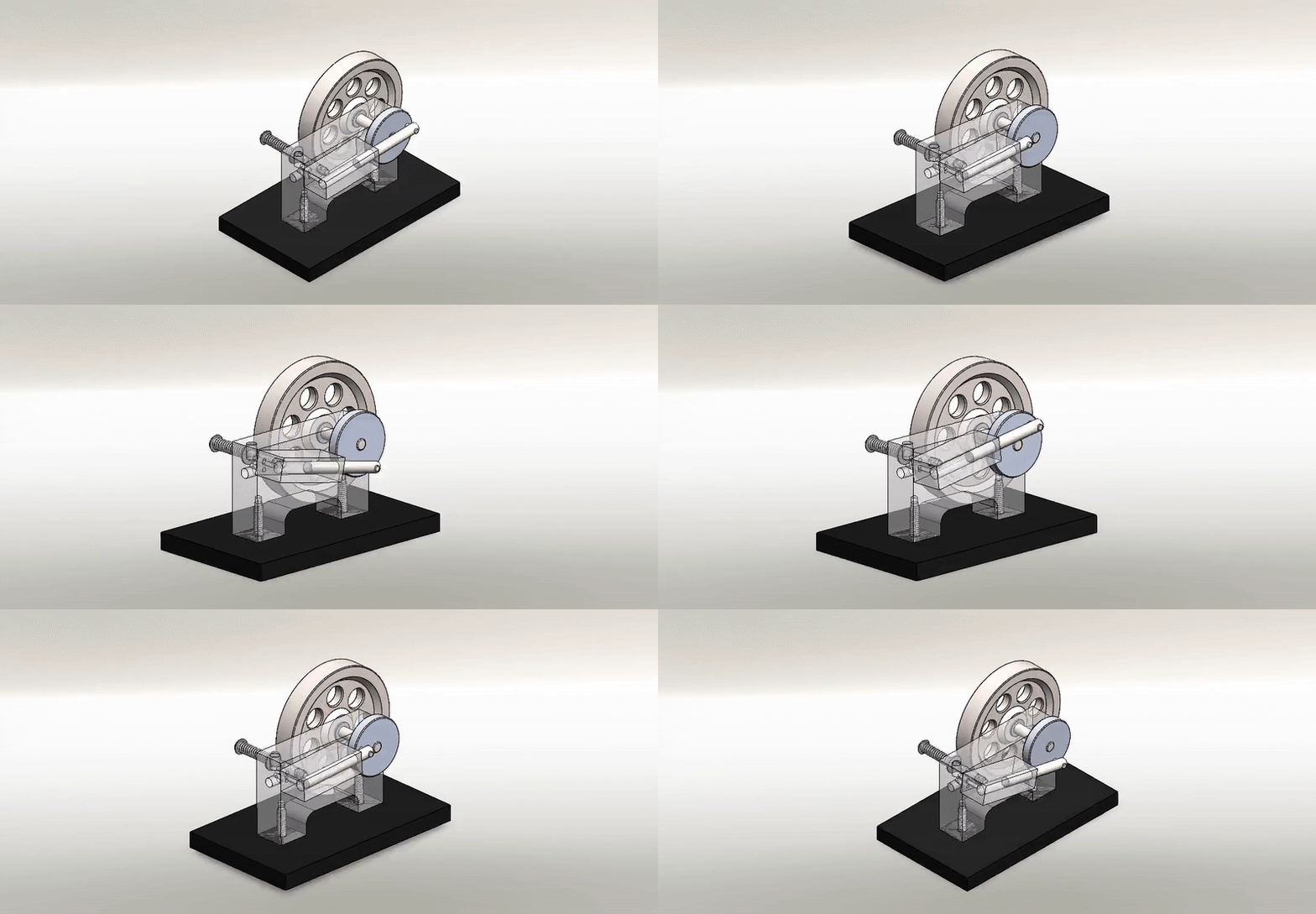
SolidWorks motion study
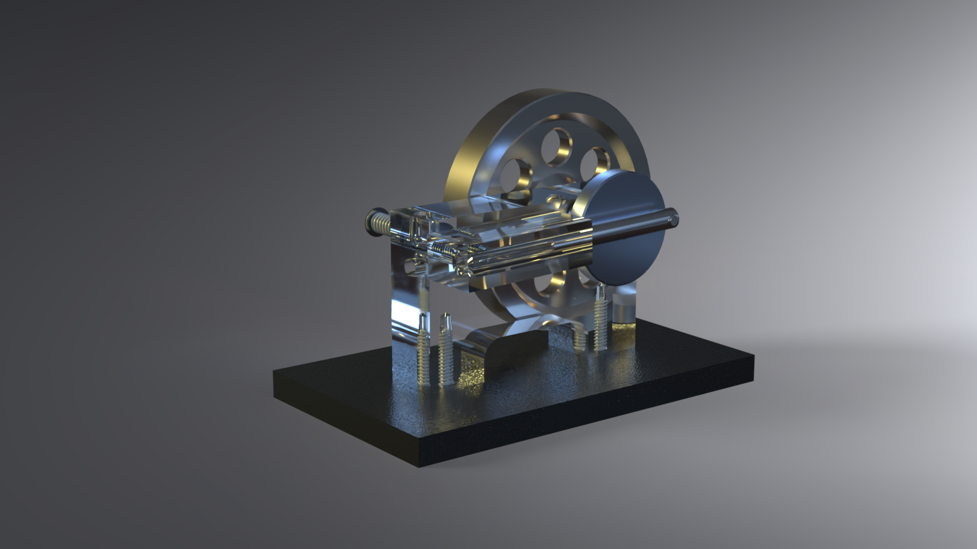
SolidWorks 3D render
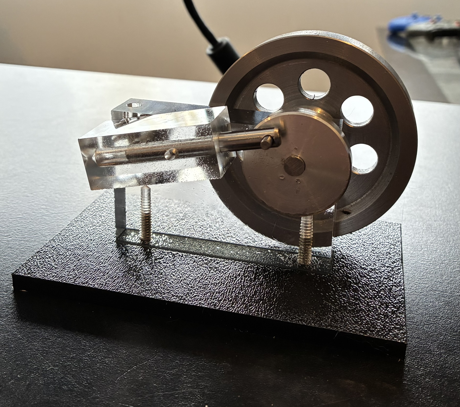
Finished build