Hardware · Embedded Systems · ECE299 Design Capstone
FM Radio Receiver
The Radio Rhino: a complete FM radio alarm clock, taken from requirements to a working prototype over one term. A custom two-layer PCB designed in KiCad, a Raspberry Pi Pico W running MicroPython, an RDA5807M tuner driving an LM386 amplifier, and a 3D-printed rhinoceros enclosure. The final firmware also hosts its own WiFi access point and serves a phone-friendly web control panel.
Overview
The Radio Rhino combines a digital clock, a settable alarm, and an FM broadcast receiver in a single 3D-printed enclosure. It was designed and built as the ECE299 Engineering Design capstone at the University of Victoria, with a partner, under the course constraint that a single Raspberry Pi Pico W programmed in MicroPython handle all information processing.
The circuit was validated on a breadboard, transferred to a custom two-layer PCB designed in KiCad, fabricated commercially, and assembled by hand. I owned the schematic capture, PCB layout, and embedded firmware.
At a Glance
- MCU: Raspberry Pi Pico W, RP2040 dual Cortex-M0+ at 133 MHz, MicroPython.
- Tuner: RDA5807M single-chip FM receiver over I²C.
- Audio: LM386N-4 amplifier into a 3 W, 8 Ω speaker.
- Display: 1.3" SH1106 OLED, 128×64, over SPI.
- Input: rotary encoder with switch, plus four pushbuttons.
- Board: two-layer PCB, DRC clean, RF keep-outs for the 2.4 GHz antenna.
- Cost: roughly $35 in components, $21.73 for fabrication.
Circuit & PCB Design
- Full schematic capture in KiCad, including the I²C pull-up network, the LM386 gain and output-filter chain, and header breakouts for every off-board control.
- Two-layer layout passing DRC before fabrication, with copper keep-out regions around the Pico W's on-module 2.4 GHz antenna and the USB connector.
- All user-interface hardware leaves the board through headers so the display, encoder, and buttons can mount to the enclosure shell.
- Gerbers and drill files exported and sent to a commercial fabricator.
Firmware
- Staged clock editing driven by the encoder: view, hours, minutes, seconds, alarm hours, alarm minutes, with the active field bracketed on screen.
- Software debouncing throughout: a 200 ms per-button guard, polled quadrature decoding with a 10 ms step filter, and a 500 ms lockout after each encoder click.
- Alarm on a PWM-driven piezo buzzer with three selectable tone presets and a two-second preview; the radio auto-mutes on trigger and its prior state is restored on dismiss or snooze.
- Selectable 12-hour and 24-hour display, converted at presentation time so the stored time and the display can never disagree.
- Firmware-side noise reduction: forced mono, soft mute, 75 µs de-emphasis, and the SMPS held in PWM mode to kill rail whine.
- Interrupt handlers only ever set flags. Every I²C transaction happens in the main loop, which eliminated a whole class of intermittent bugs.
WiFi Control Panel
The Pico W's CYW43439 radio hosts its own access point, and the device serves a phone-friendly web panel at radiorhino.clock through a catch-all DNS responder. Frequency, volume, mute, alarm time, and display format are all settable from a phone, and a one-tap control syncs the device clock from the phone's own time.
The original design joined an existing network instead. That approach was abandoned after the failure was traced to WPA3-transition security on phone hotspots, which the CYW43 driver can see in a scan but cannot join. Access-point mode removed the dependency entirely.
Enclosure
- Rhinoceros-themed shell modelled in SolidWorks, with a dimensioned multi-view drawing produced for fabrication.
- Cutouts sized for the OLED window, encoder shaft, speaker grille, four buttons, and the telescoping antenna.
- Printed in multiple parts and assembled around the populated board.
Debugging Highlights
- Amplifier saturation. First bring-up produced distorted audio. Tracing the audio path against the schematic with a scope isolated a DC bias at the amplifier input created by R4; omitting it restored clean reproduction.
- Failing microcontroller. The Pico W started booting intermittently. Rails measured healthy in the failed state and the module always enumerated when BOOTSEL was held, which proved the core, crystal, and USB path were fine and condemned the QSPI flash. The module was floated off with low-temperature alloy and replaced.
- Display shutting off on redraw. Traced to a broken reset-line wire; the SH1106 wakes from hardware reset with the display off, so every redraw exposed it.
- Dead buttons. Two off-board buttons never registered. The fault was in hand-soldered flying leads, re-made with pre-tinned, fluxed joints and strain relief.
Testing & Results
- Net-by-net continuity and rail short checks before every power-up.
- Ten presses per button and ten detents per direction, verifying exactly one registered event each.
- Volume sweep across every step, band-edge wrap-around, and mute verification on live stations.
- A 20-cycle power-replug stress test on the replacement module, booting normally every cycle.
- End-to-end alarm flow run against all three tone presets, from both the encoder and the web panel, in both display formats.
- All ten test rows in the final report pass, and the prototype meets every mandatory project requirement.
Gallery
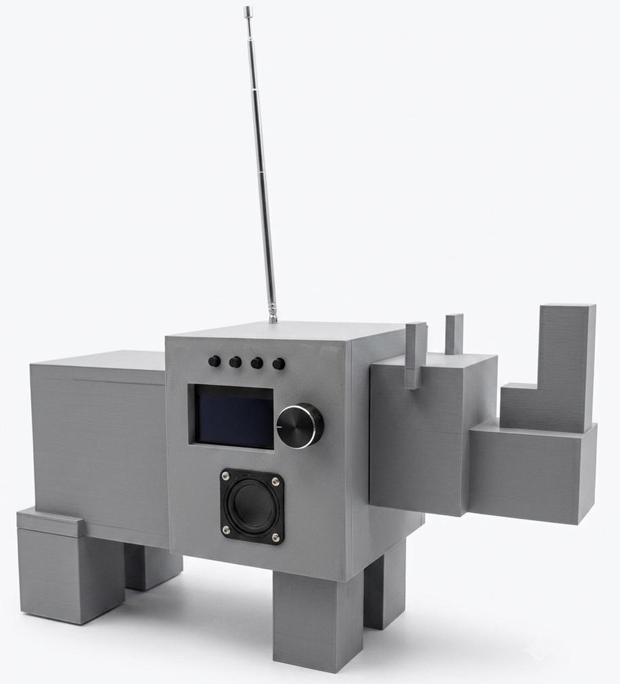
Finished build
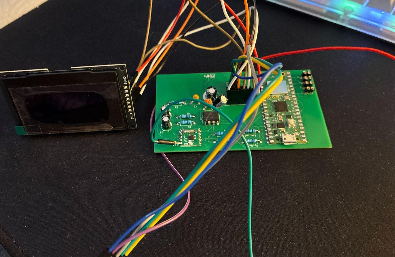
Assembled PCB
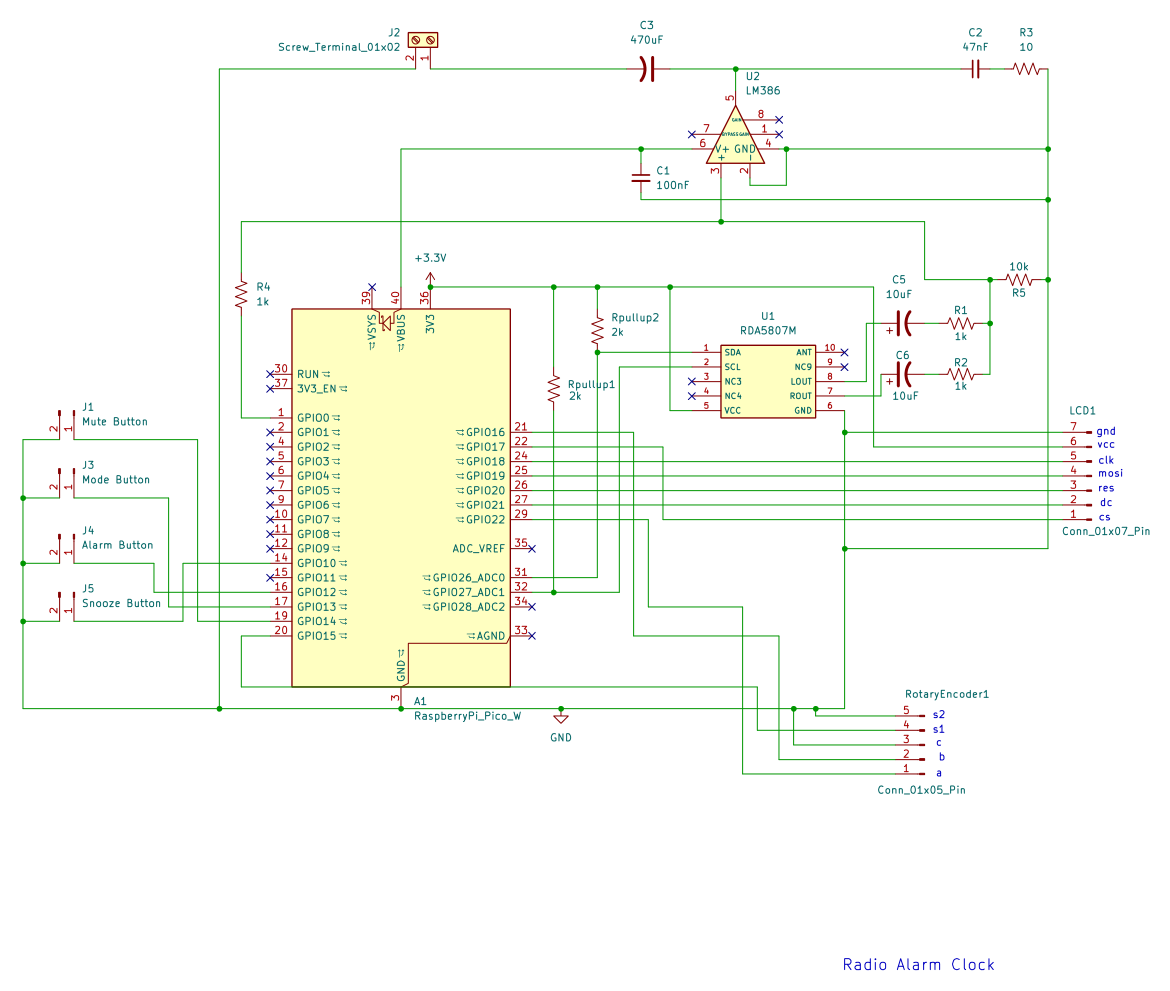
KiCad schematic
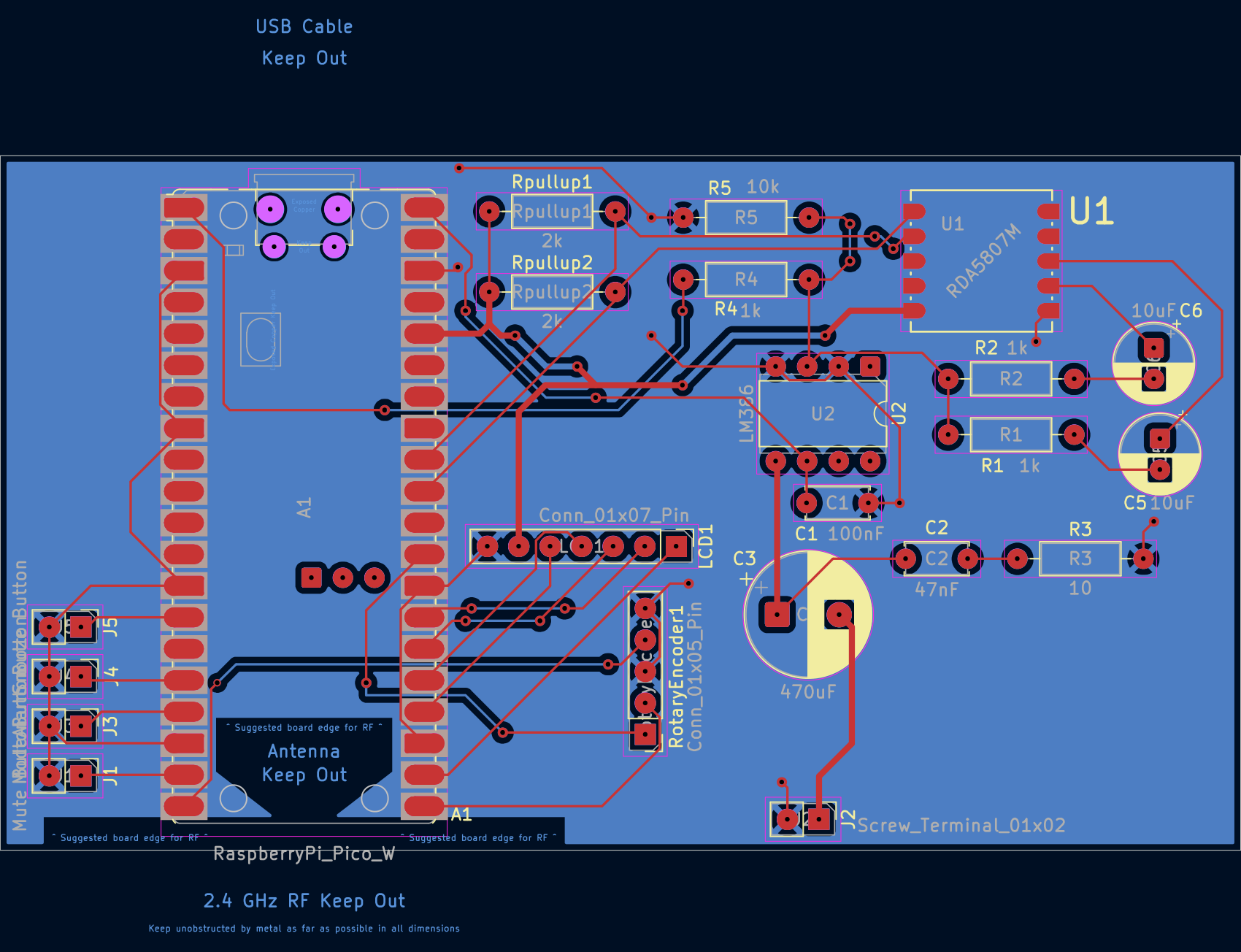
PCB layout as fabricated
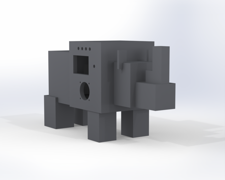
Enclosure render
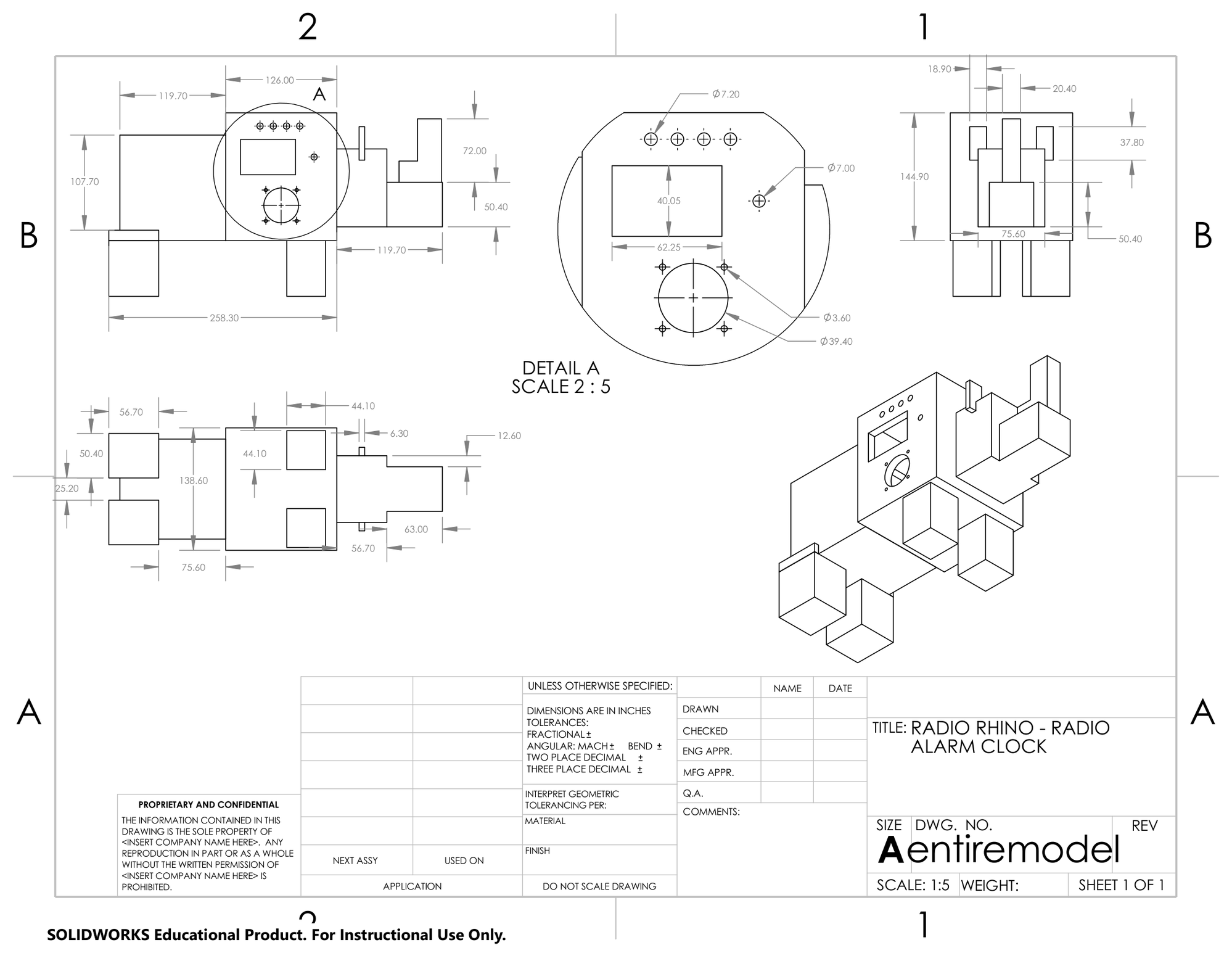
Enclosure engineering drawing
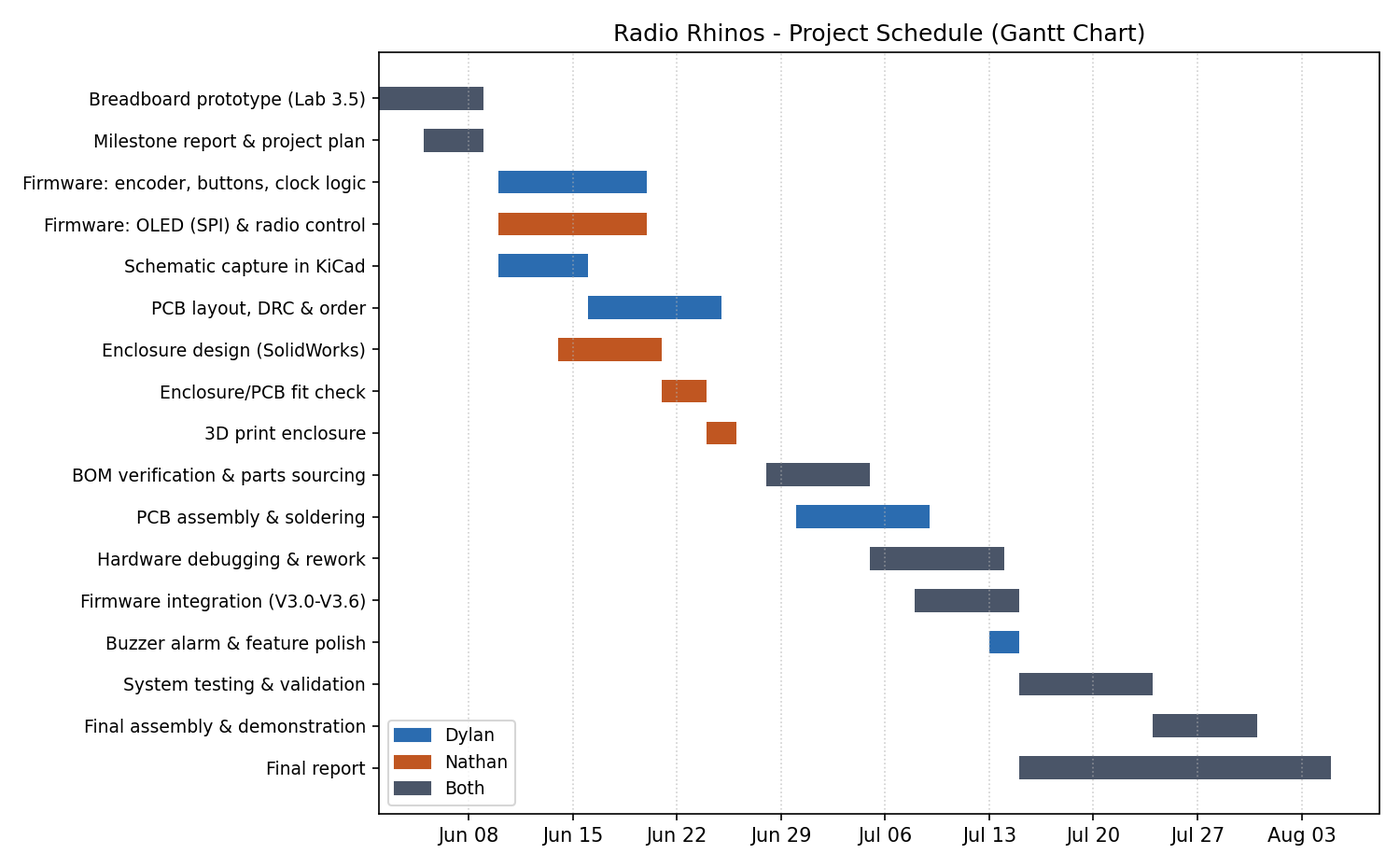
Project schedule
Project Complete
Built, demonstrated, and documented for ECE299 Engineering Design at the University of Victoria. The prototype meets every mandatory requirement and adds a WiFi web control panel, selectable alarm tones, adjustable display brightness, and an idle screensaver with playable mini-games on top of the required scope.